Non-line-of-sight imaging using phasor-field virtual wave optics
Introduces the virtual-wave formulation for propagating and focusing non-line-of-sight measurements.
Nature Communications 2026
1University of Wisconsin–Madison2Politecnico di Milano3University of Arizona
Recovering how light travels between hidden surfaces.
One wall measurement dataset. Independently focused virtual illumination and detection.
Experimental result
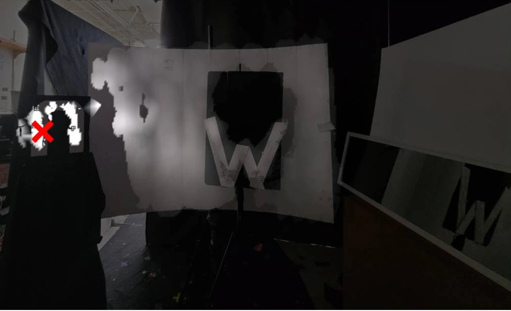
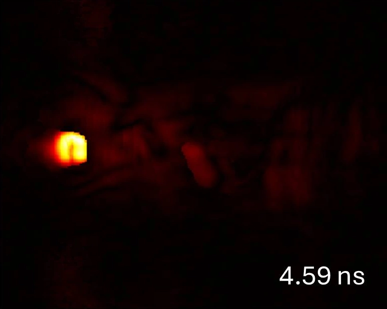
Selected experimental frames from Fig. 3. Each focus reuses the same acquisition. Separate light paths produce the delayed responses; these frames do not describe a single path through every object.
Each frame is rescaled to its own maximum to reveal weak indirect transport; displayed brightness is not directly comparable across time. Later residual energy near the focus includes temporal sidelobes.
The idea
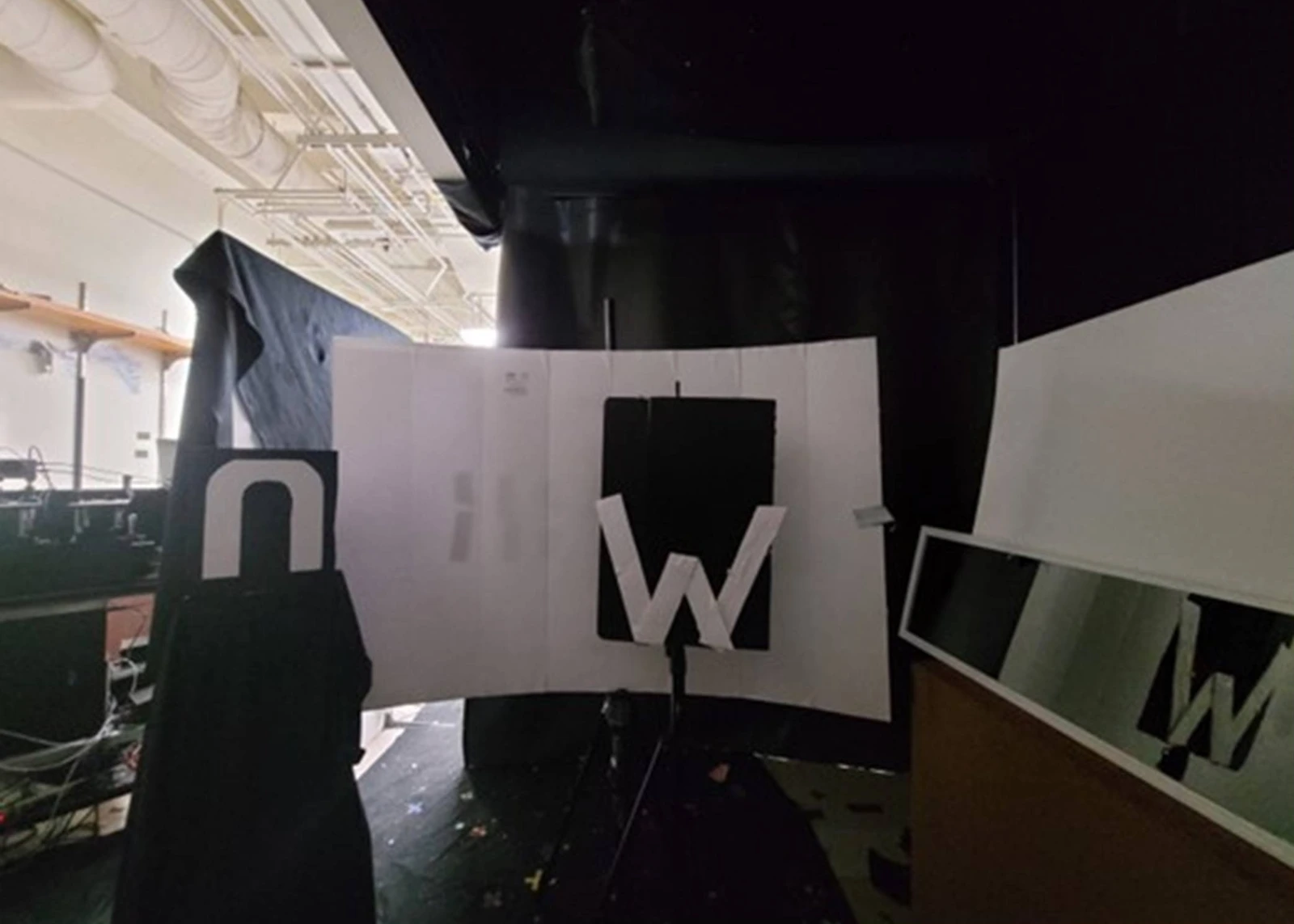
From seeing hidden objects to measuring the light between them.
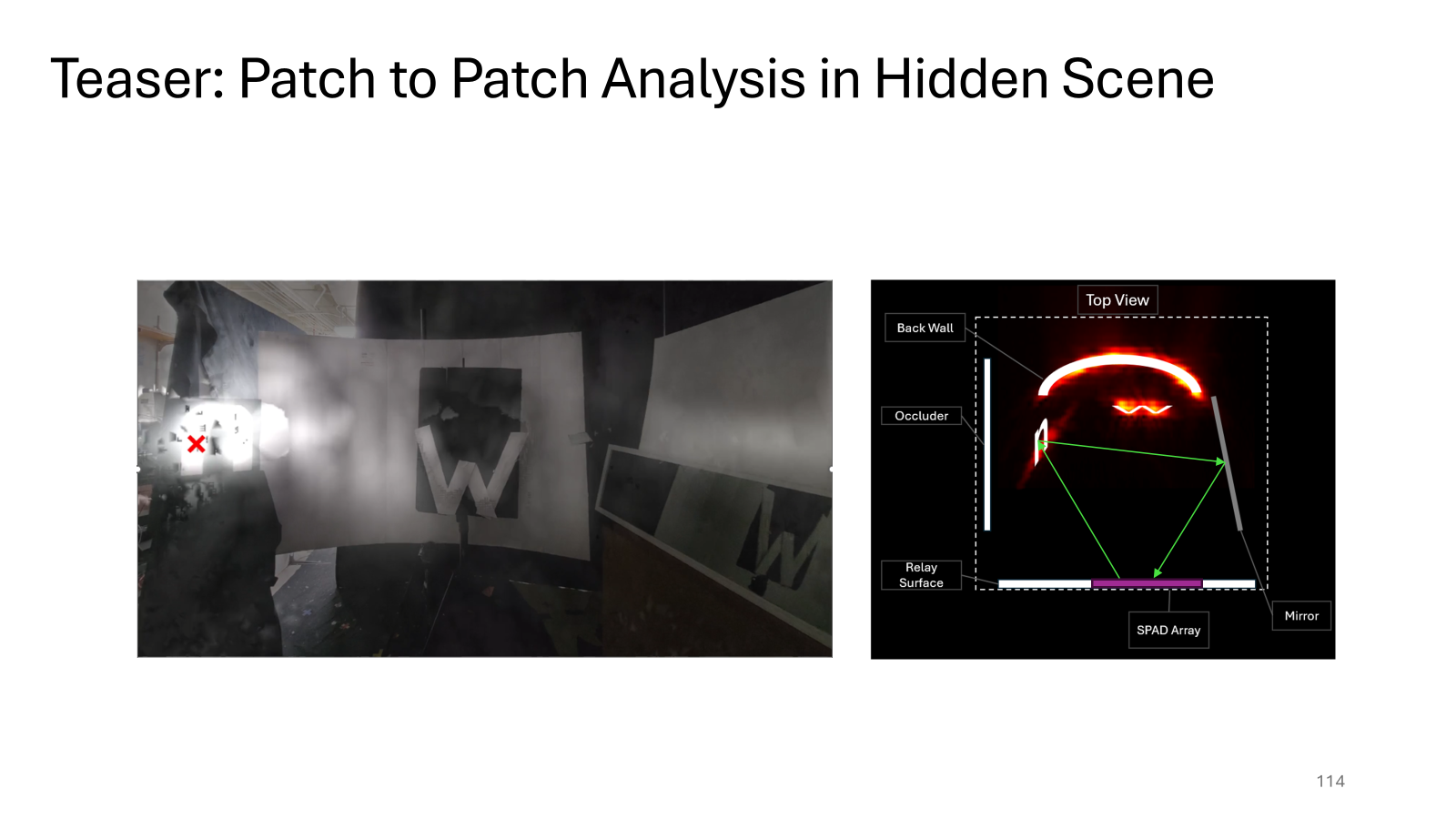
Non-line-of-sight imaging uses reflections from a visible wall to reconstruct hidden objects. We ask a further question: if we virtually illuminate one hidden patch, where does its light go, and when does it arrive?
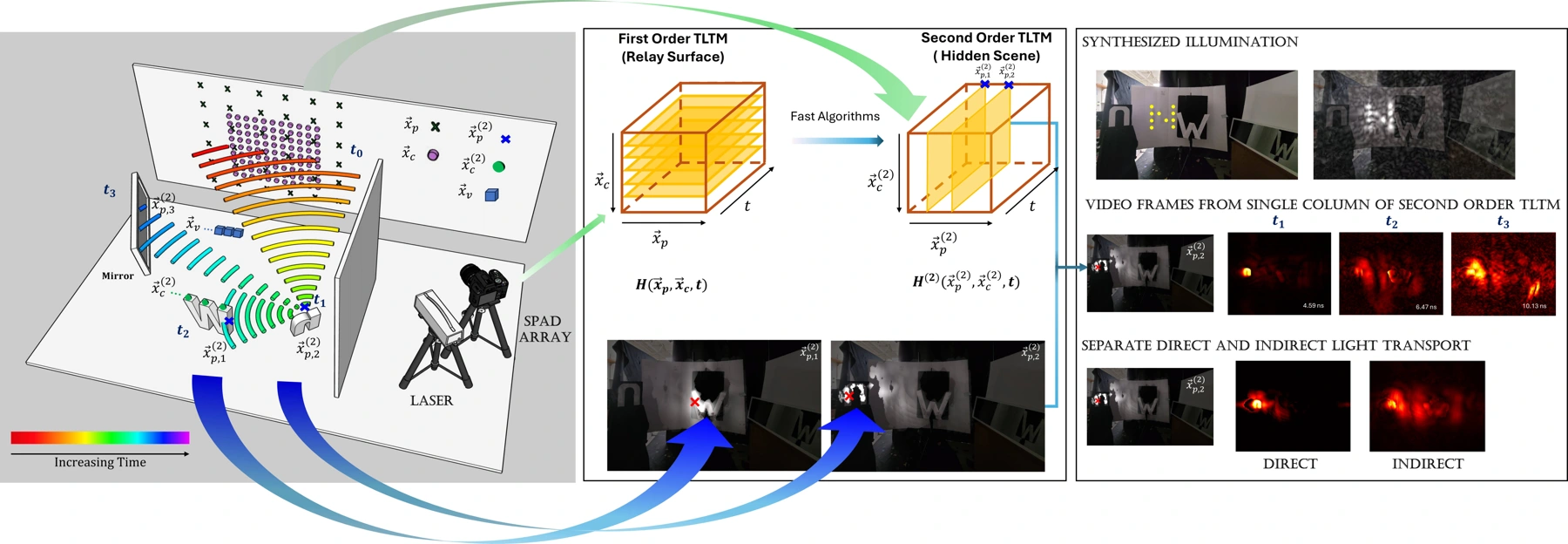
We measure transient light transport on the relay wall, then computationally focus illumination and detection at independently chosen hidden locations. The resulting TLTM-2 describes time-resolved transport between hidden-surface patches.
From wall measurements to virtual experiments
inside a hidden scene.
How it works
All focusing happens computationally,
after the measurements are captured.
Fast Rayleigh–Sommerfeld diffraction (RSD) reconstruction combines the source measurements before imaging. FFT-based propagation then reconstructs each transient frame efficiently, making time-resolved virtual illumination and detection practical.
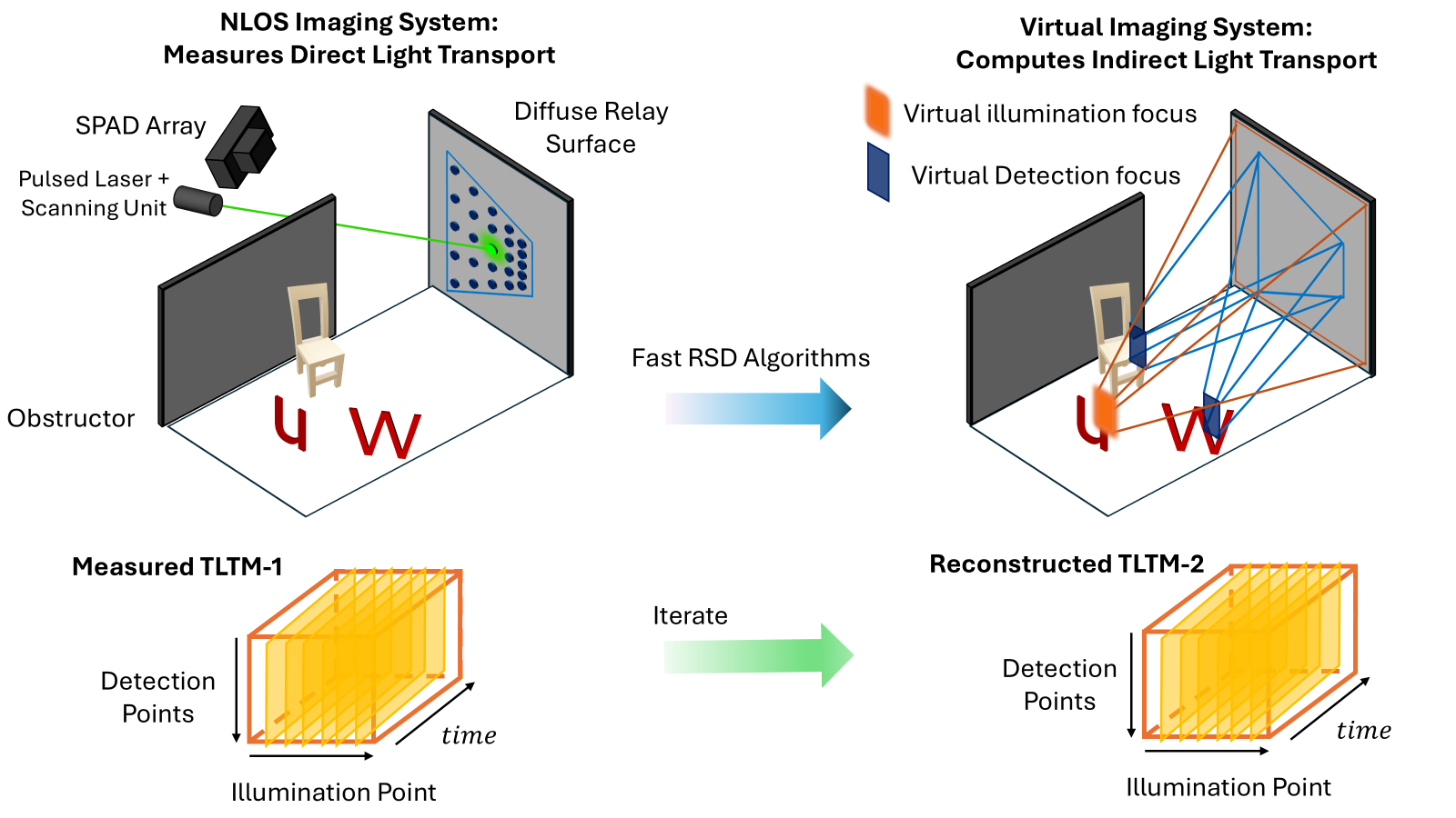
A dense pulsed-laser scan and a gated 16 × 16 SPAD array record the response for each sampled illumination–detection pair, forming TLTM-1.
After estimating the hidden surfaces, we synthesize a virtual pulse and apply delays and weights across wall samples to focus it onto a selected patch.
Computational receiving focus reconstructs the transient response across the hidden scene. Illumination and detection locations are selected independently.
One illumination patch gives one transient video: a column of TLTM-2. Repeating over illumination patches builds the matrix.
Each frame selects a different hidden source patch and sums its response over time. This movie scans focus locations; it does not show a single pulse evolving.
Supplementary Movie 2 · Watch without the photograph overlay (Movie 3)
What TLTM-2 reveals
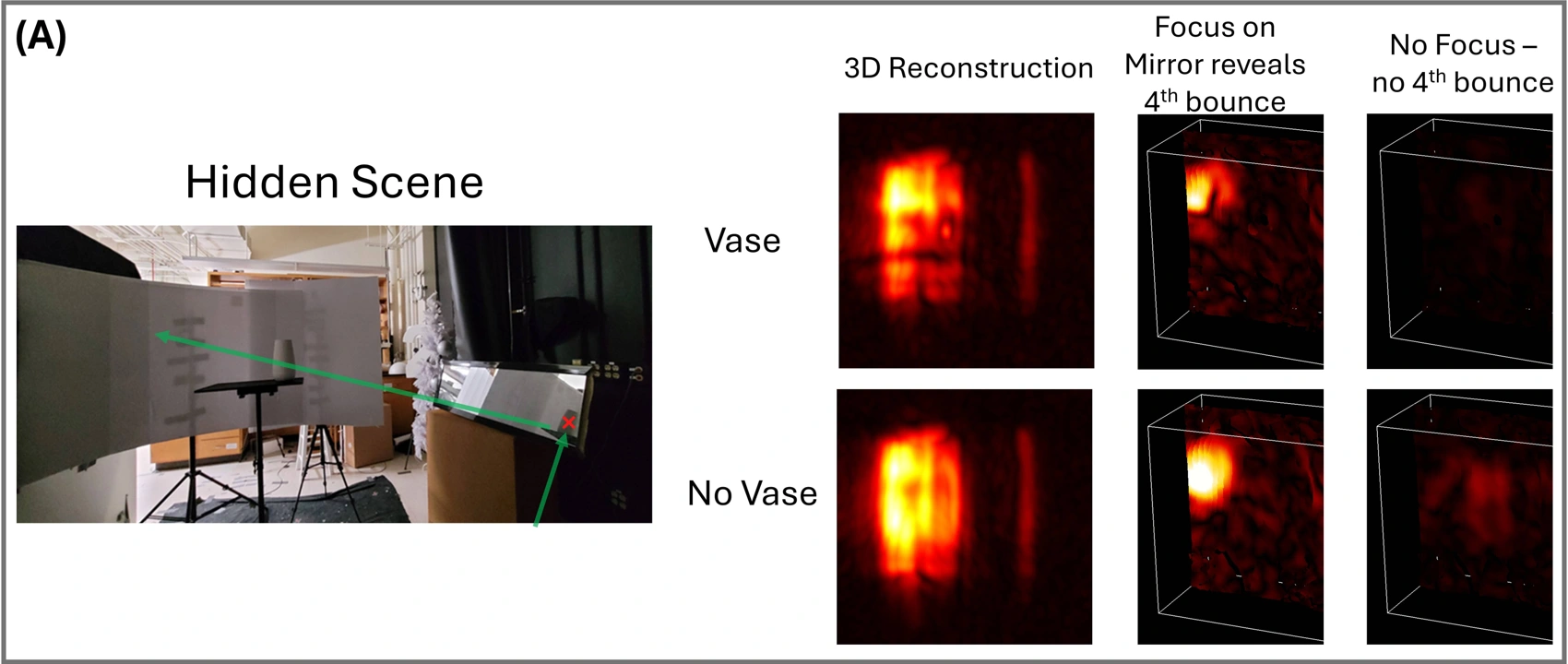
Virtual illumination focused on a mirror reveals light reaching the back wall. A vase blocks part of this path and casts a soft shadow.
Removing the vase and its stand removes the shadow at the corresponding time. The control connects the reconstructed feature to a physical change in the scene.
Clear water produces distinct reflections from the tank’s surfaces. Adding milk produces persistent scattering within the volume and attenuates the back-wall reflection.
These transient differences reveal information about light–matter interactions beyond surface geometry.
Hidden scene
Hidden scene
Use the time labels inside each movie to compare propagation. Playback positions are independent.
Applications
Use timing and spatial diversity
to change what the reconstruction shows.
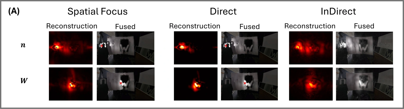
Geometry-dependent time gating separates the dominant single-hidden-surface return from later multi-bounce transport. Direct and indirect components use separate display ranges because the indirect signal is much weaker.
Current limits & outlook
The prototype’s sparse SPAD sampling limits the virtual focus. Finite spatial and temporal resolution produce residual illumination that can overlap weak multi-bounce signals. Reliable surface estimates, calibration, and sufficient photons remain essential.
Denser sampling over a suitable relay aperture can improve virtual focusing.
Denser SPAD sampling over a suitable relay aperture can sharpen a sampling-limited virtual focus without increasing computational complexity. For direct beamforming with fast RSD, the dominant reconstruction cost is O(kN³ log N) per illumination focus, independent of SPAD pixel count, where k is the number of transient frames and N³ is the number of voxels in the reconstruction grid. More pixels will still require additional data storage and handling.
Future direction
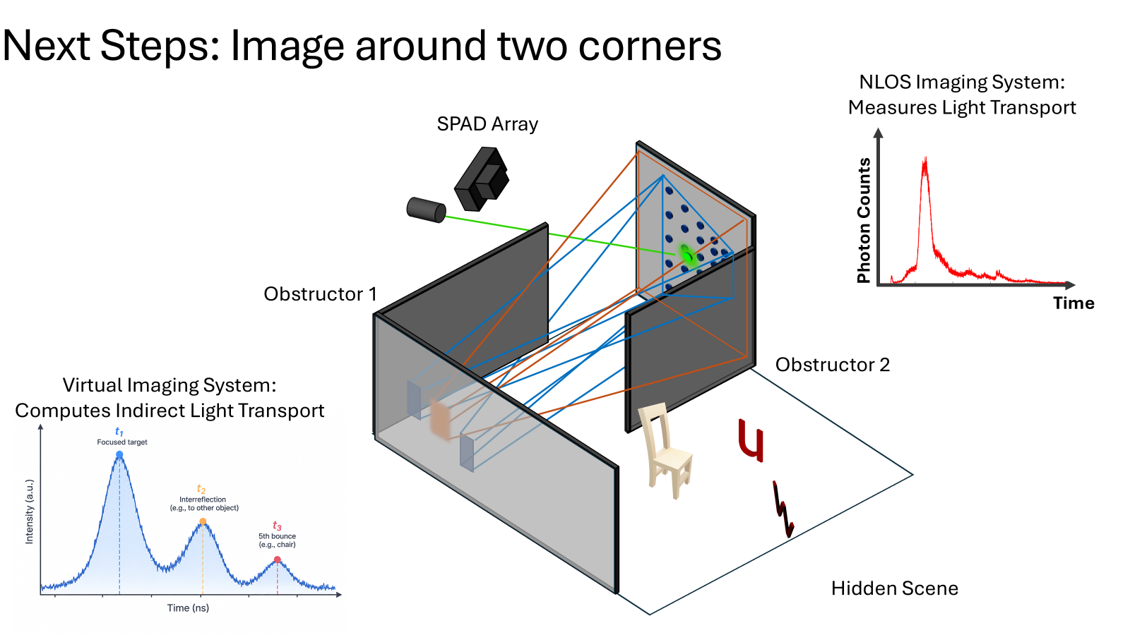
Further iteration could turn reconstructed hidden surfaces into new virtual relay surfaces, extending imaging around a second corner. The experiments here demonstrate TLTM-2; a two-corner reconstruction remains a future goal.
Acknowledgments
The UW–Madison authors acknowledge support from the Air Force Office for Scientific Research (FA9550-21-1-0341, FA9550-26-1-B169) and the Defense Advanced Research Projects Agency through the DARPA REVEAL Project HR0011-16-C-0025.
Reference
Sultan, T., Brandt, E., Masumnia-Bisheh, K. et al. Iterating the transient light transport matrix for non-line-of-sight imaging. Nature Communications 17, 8951 (2026). doi:10.1038/s41467-026-75177-4
@article{Sultan2026,
  author  = {Sultan, Talha and Brandt, Eric and Masumnia-Bisheh, Khadijeh
             and Riccardo, Simone and Polynkin, Pavel and Tosi, Alberto
             and Velten, Andreas},
  title   = {Iterating the transient light transport matrix
             for non-line-of-sight imaging},
  journal = {Nature Communications},
  year    = {2026},
  volume  = {17},
  pages   = {8951},
  doi     = {10.1038/s41467-026-75177-4}
}